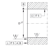
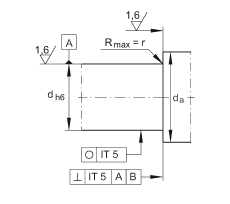
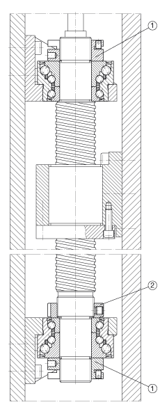
|  |       | | | | | Adjacent structural design | | | | | Adjacent structural design | | | | Both sides of the screw support the positioning ball bearing configuration.
The number of turns turned indicates the position of the fixing bolt recommended by INA (see table or "Component" below). | | | |
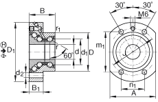
| | | | | | A | 55 mm | | | B1 | 18 mm | | | D1 | 75 mm | | | d1 | 28 mm | | | d2 | 6,8 mm | | | da max | 35 mm | | | da min | 20 mm | | | J | 58 mm | | | r1 min | 0,6 mm | | | rmin | 0,3 mm | |
| | | | | | | | note!
The bearing must be subjected to a continuous load in the main load-bearing term H. |
| | m | 0,53 kg | | | Ca | 17900 N | | | Basic dynamic load rating,Axis term,← |
| | C0a | 28000 N | | | Basic static load rating,Axis term, ← |
| | Ca | 37000 N | | | Basic dynamic load rating, Axis term, main bearing item H, → |
| | C0a | 83000 N | | | Basic static load rating,Axis term,Main bearing item H,→ |
| | nG Fett | 2600 1/min | | | Limit speed during grease lubrication |
| | MRL | 0,35 Nm | | | caL | 500 N/µm | | | caL | 950 N/µm | | | ckL | 140 Nm/mrad | | | Mm | 0,278 kg x cm^2 | | | Weight moment of inertia of rotating inner ring |
| | | 5 µm | | | Axis jump
The Axis jump of the screw-supported bearing configuration is based on the inner ring rotation. |
| | | 4 x M6 | |
|
|
 Component